Create a hexpansion
Hexpansions are accessories that plug into the badge's expansion connectors. Almost anything can be a hexpansion - the simplest hexpansion is just a piece of 1mm card cut into the right hexagonal shape. Here are some community examples: (1)
- If you want to add your hexpansions to this gallery, you can add them to the registry or add them to this issue or let us know on the IRC/Matrix! We'd love to feature all of your creations!
 OG Hexpansion by kliment
 👀 VIEW FILES
 Ducks hexpansion by Tiff
 EMF ducks sixties style flying porcelain ducks
Link: Instagram
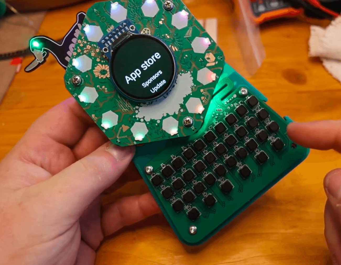 Keyboard hexpansion by Alex
  Goosespansion by Skyler Mansfield
 👀 VIEW FILES
 LED Filament hexpansion by John Thurmond
 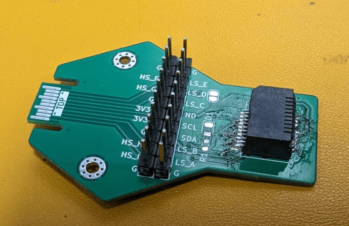 Interposer by The Untitled Goose
 💰 BUY HERE
👀 VIEW FILES
 Plotter hexpansion by Danny Walker
 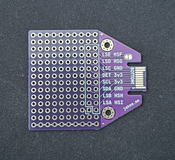 Protoboard Hexpansion by Jake Walker
 💰 BUY HERE
 Hex-Drive and Hex-Dev by Team RobotMad
 💰 BUY HERE
 EEH Hexpansion by Matt
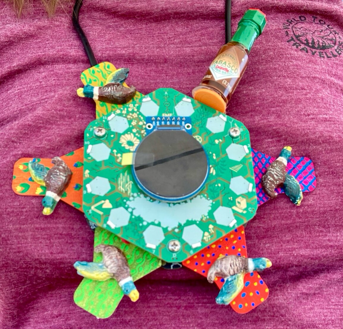
 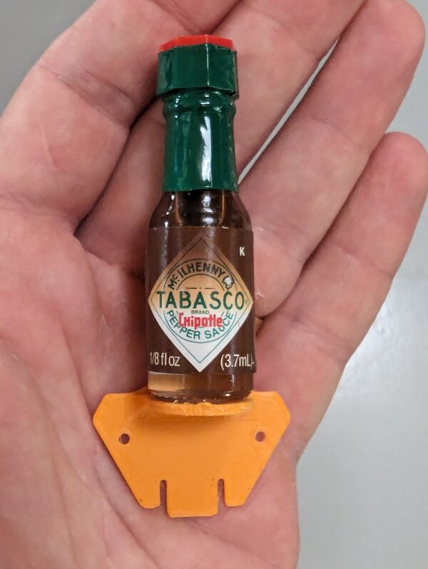 Emergency Hot Sauce hexpansion (chipotle flavor) by John Thurmond
  Maker Space badge by Dan
 Link: GitHub
 Floppy disk "Flopagon" by Nathan Dumont
 👀 VIEW FILES
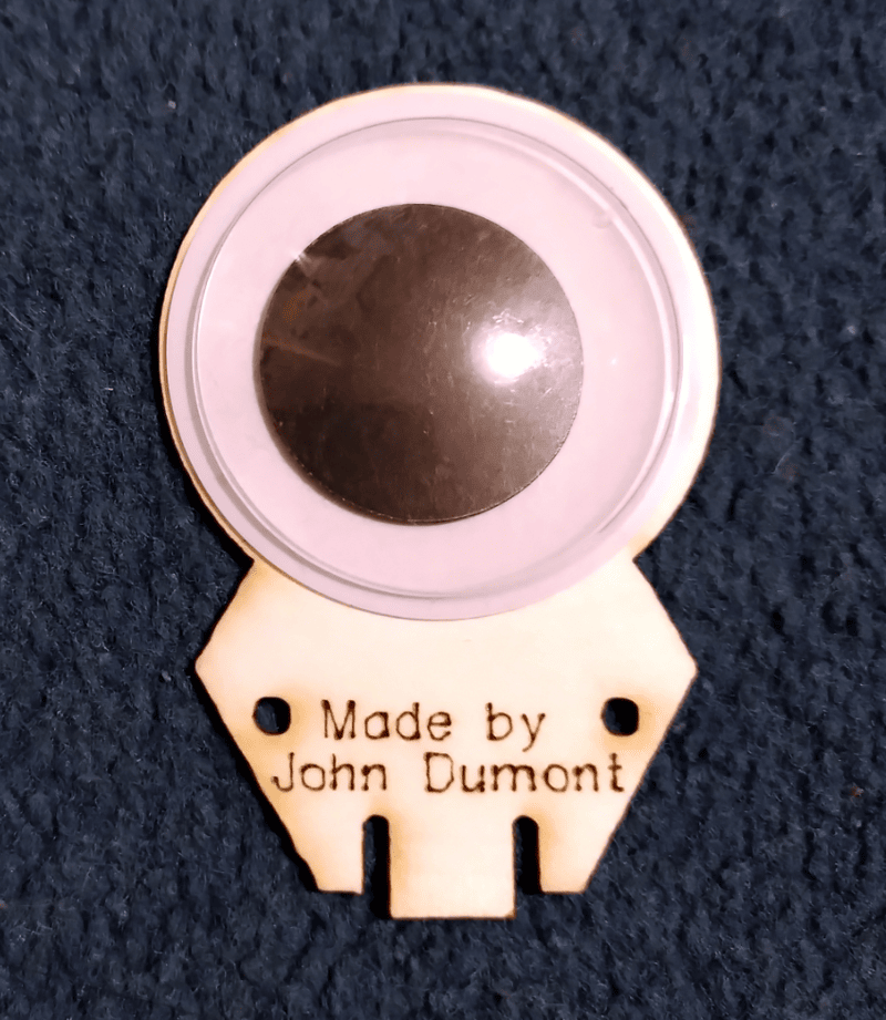 40mm Googly Eye by John Dumont
 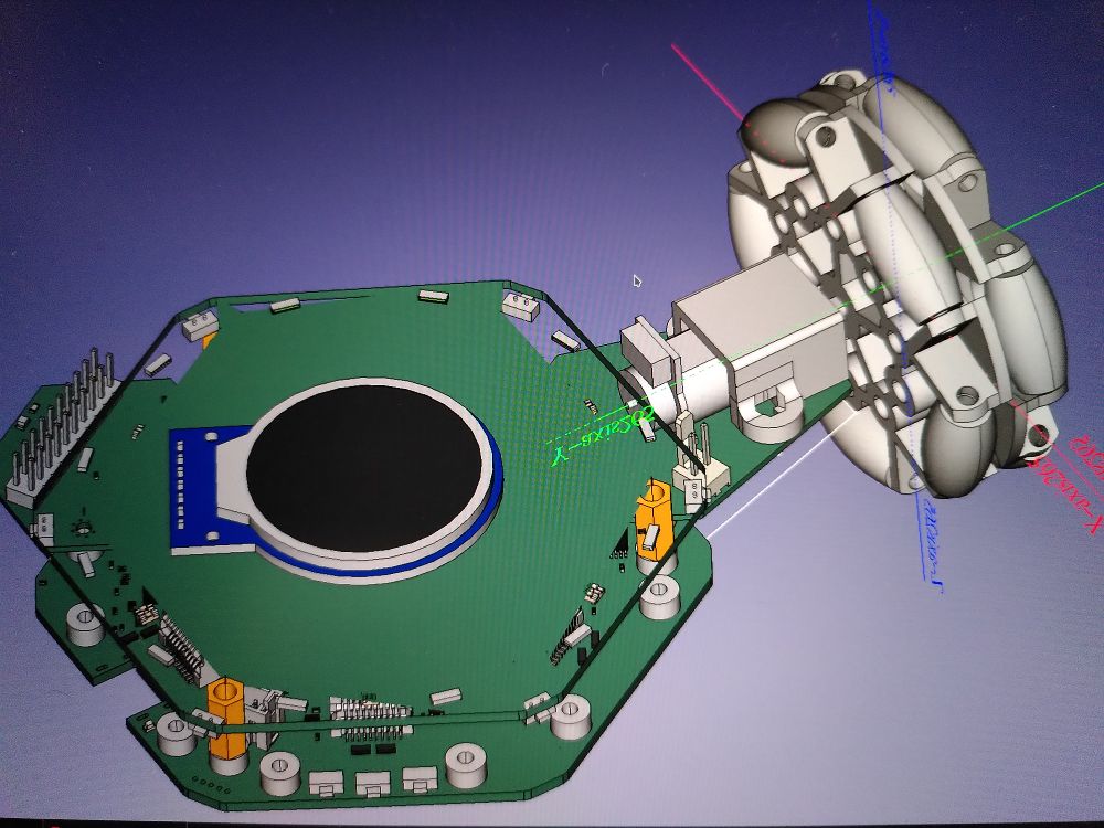 Omni wheel by Nathan Dumont
 👀 VIEW FILES
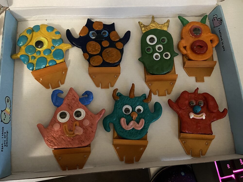 Little Monsters by Talula
 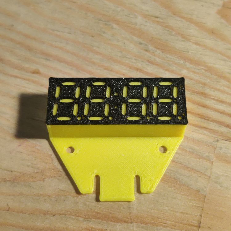 7-Segment display by Iain Yarnall
 🖨️ PRINT ME
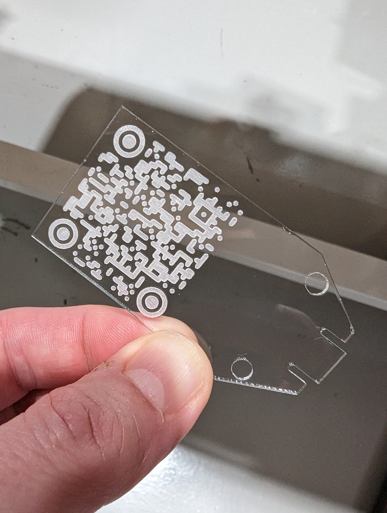 Mysterious QR Code by grajohnt
 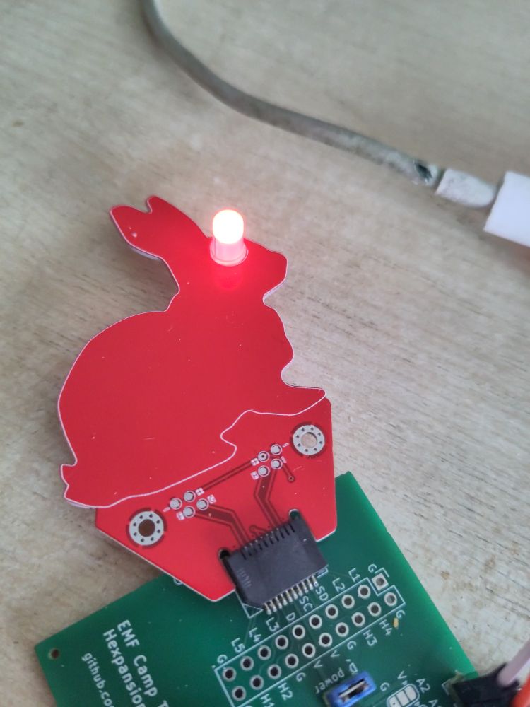 That Rabbit by Dan
 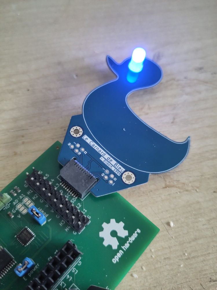 Le Carnard de Bleu by Dan
 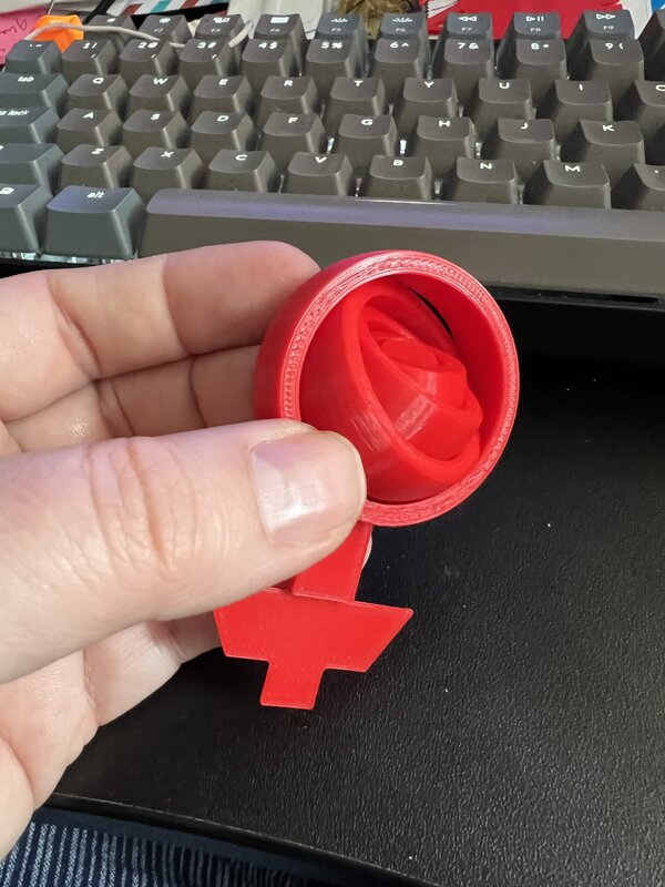 Fidget Spinner by Catherine
 🖨️ PRINT ME
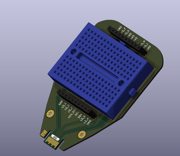 Breadbeard Hexpansion by Danny Walker
 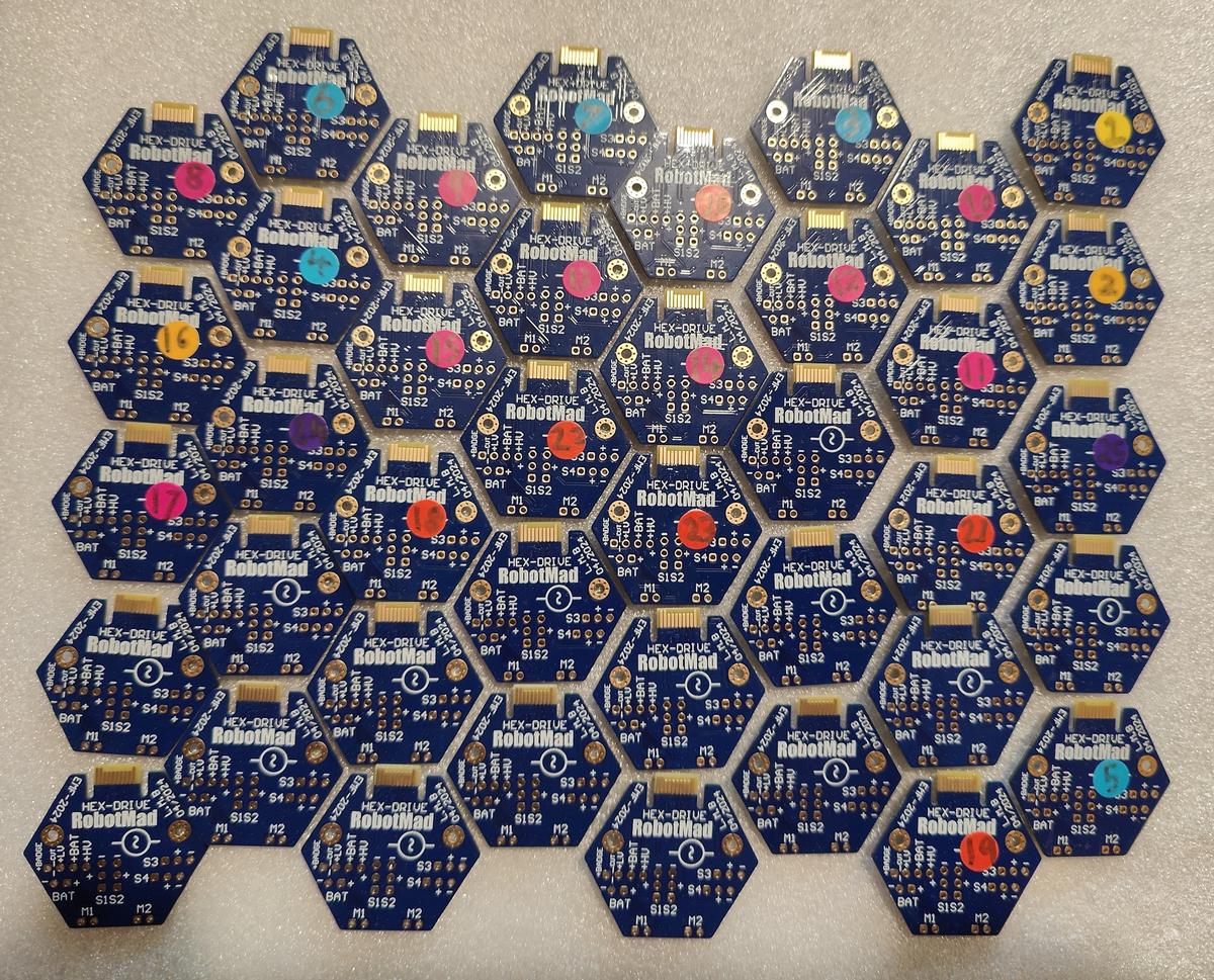 Hex-Drives by Team RobotMad
 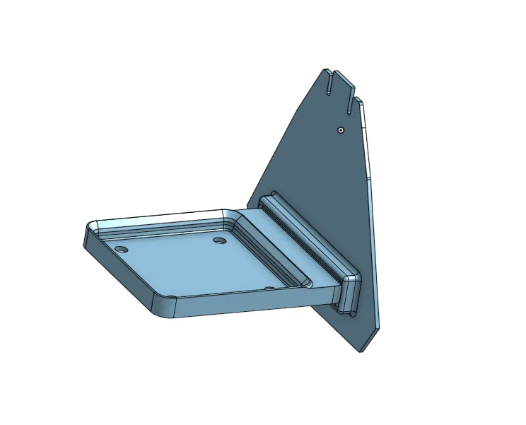 Gridfinity expansion hexpansion by Jack Fitton
 🖨️ PRINT ME
 GCHQ.NET markers by GCHQ.NET
 Link: GCHQ
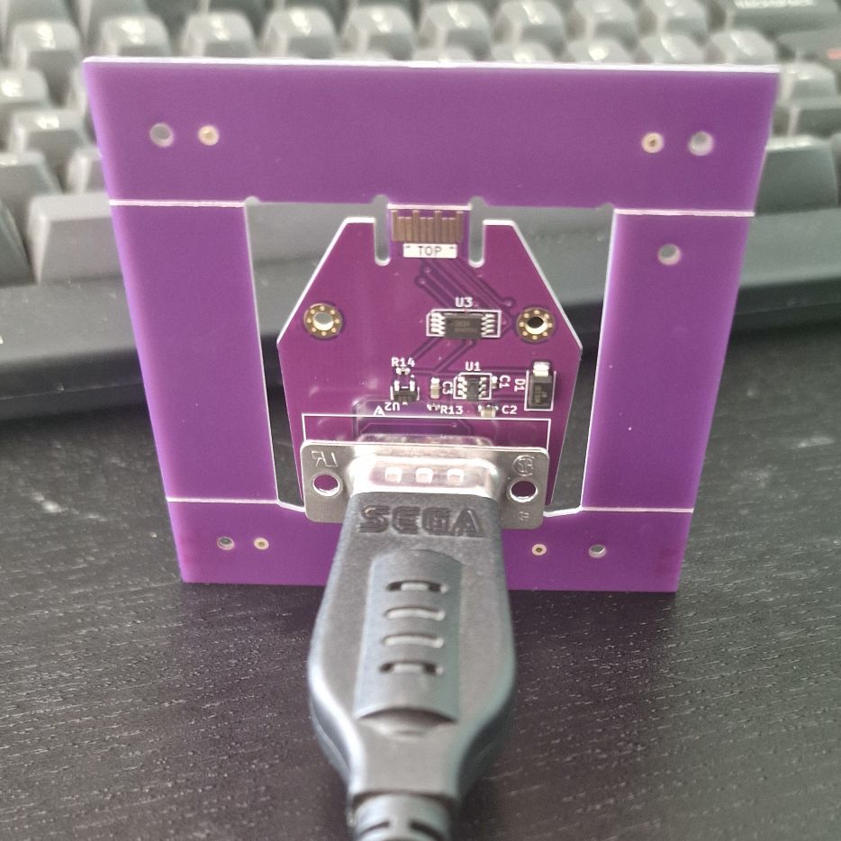 Megadrive controller by Matthew Wilkes
 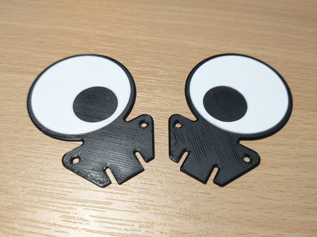 Eye hexpansion by Alistair
 🖨️ PRINT ME
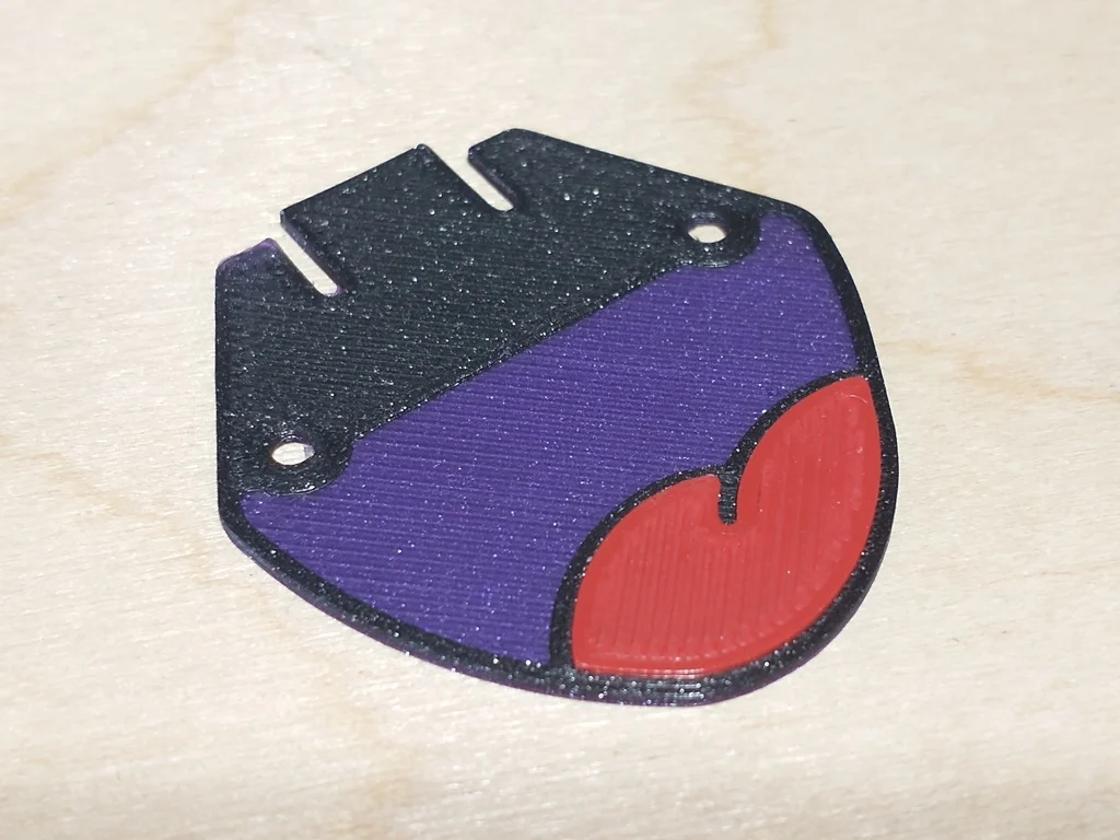 Smile hexpansion by Alistair
 🖨️ PRINT ME
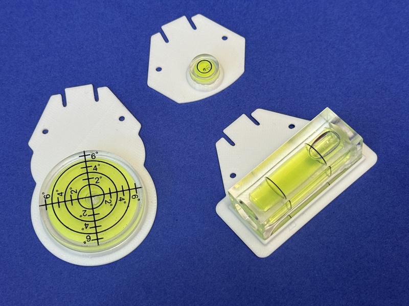 Spirit level hexpansions by Andy Piper
 🖨️ PRINT ME
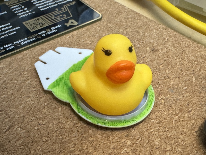 Duck pond hexpansion by Andy Piper
 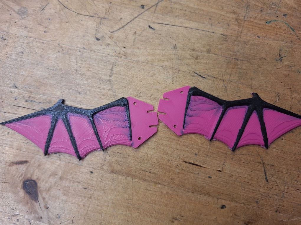 Bat wing hexpansions by clayalien
 🖨️ PRINT ME
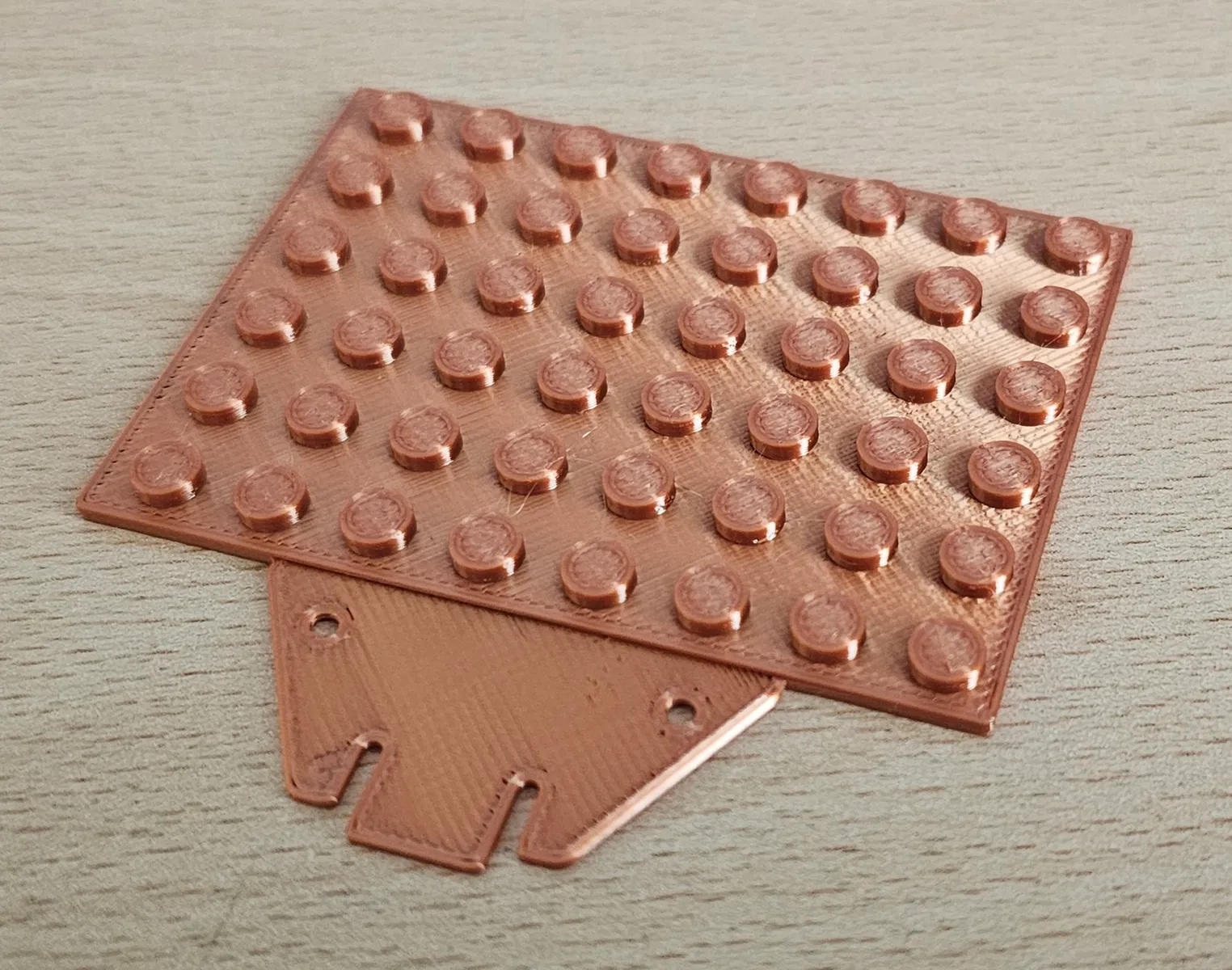 Not lego baseplate hexpansion by adie
 🖨️ PRINT ME
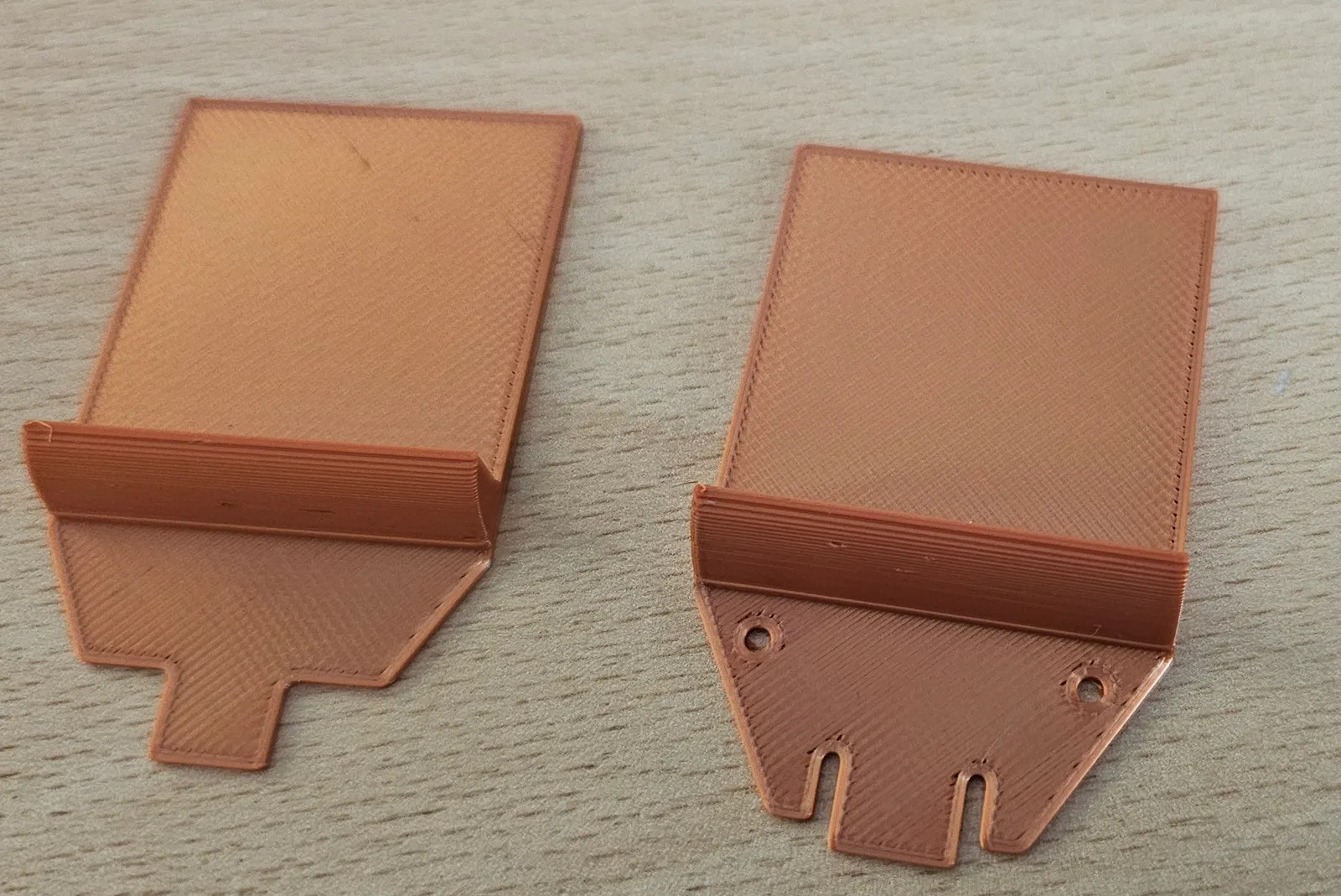 Display platform hexpansion by adie
 🖨️ PRINT ME
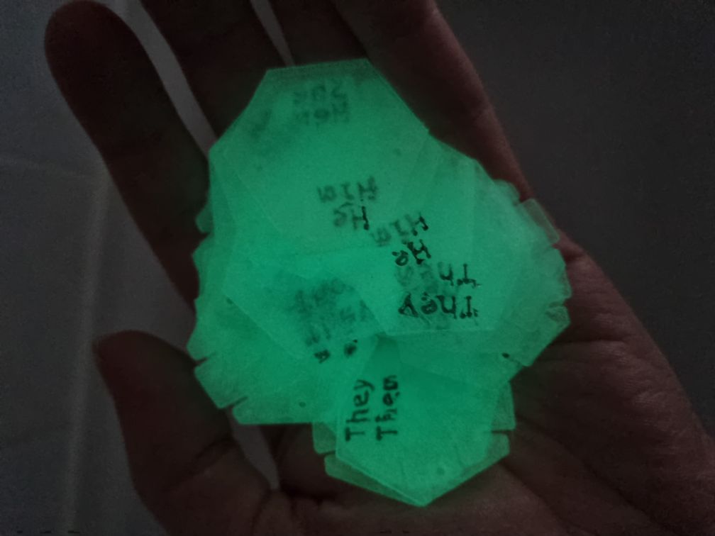 Glowing pronoun hexpansions by Emily S
 🖨️ PRINT ME
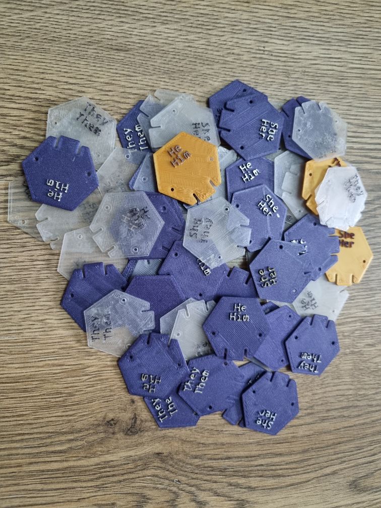 Pronoun hexpansions by Emily S
 🖨️ PRINT ME
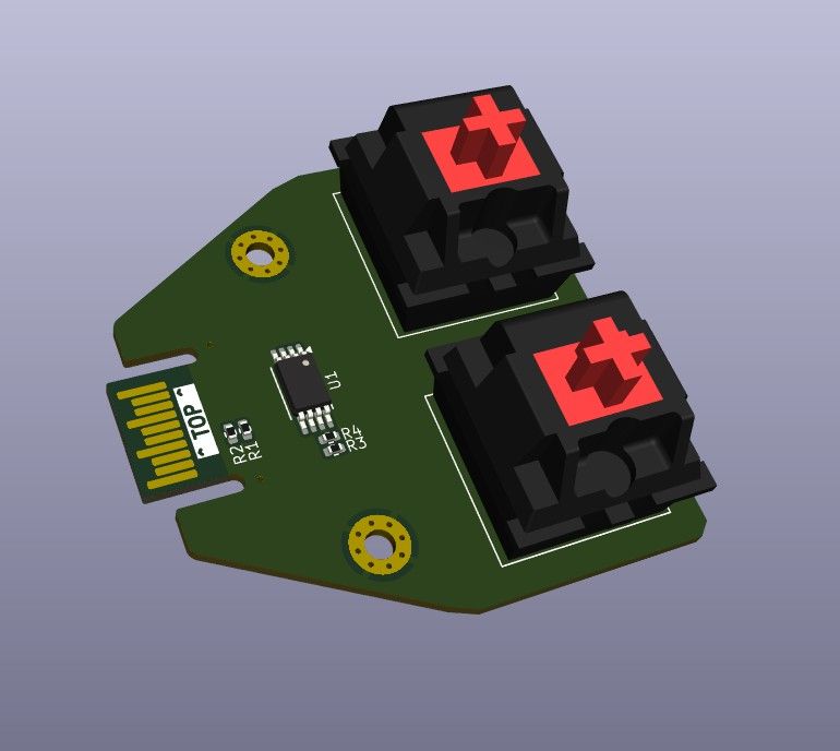 Keyboard by Bob
 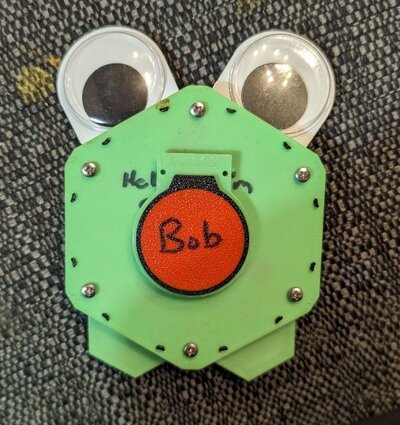 Frog prototype by Bob
  Many eyes by Bob
 👀 VIEW FILES
👀 VIEW FILES
 HUB75 hexpansion by dratini0
 👀 VIEW FILES
 Blank Hexpansion by Nathan Dumont
 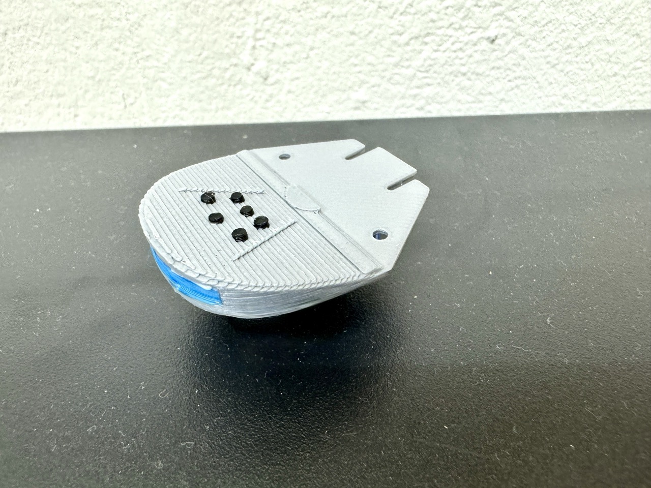 Corellian Freighter Hexpansion by Andy Piper
 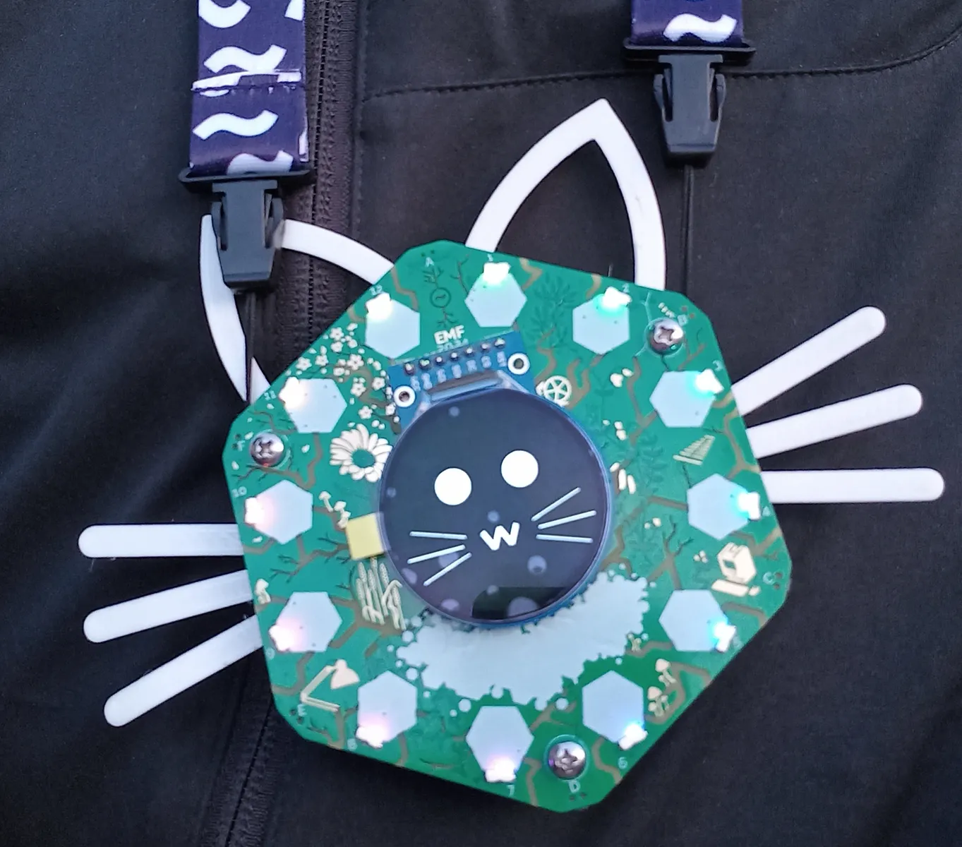 Cat ears and whiskers by catnerd
 🖨️ PRINT ME
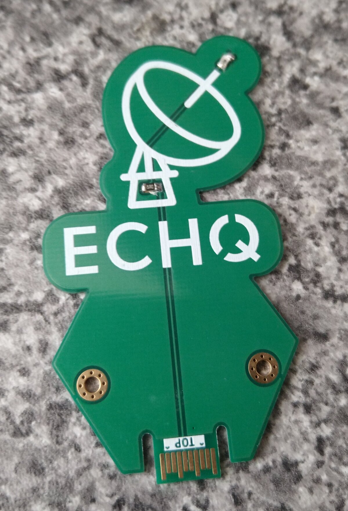 ECHQ hexpansion by ECHQ village
 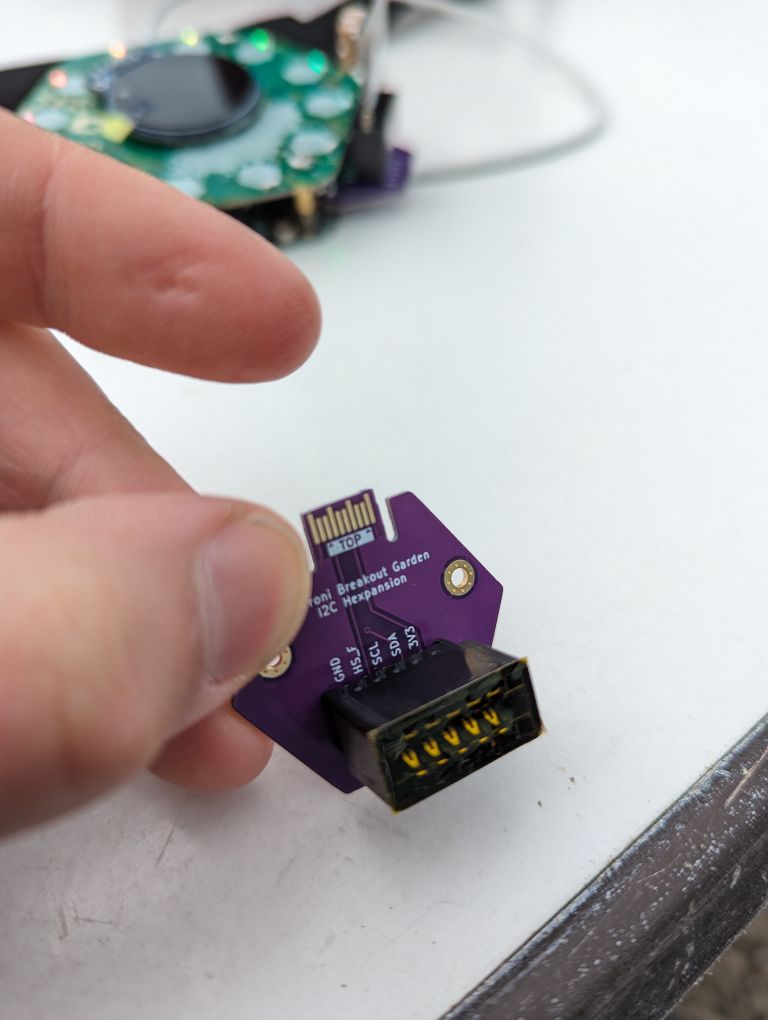 Pimoroni Breakout Garden I2C by James Sutton
 Link: GitHub
 Hexaspansaputer (hexpansion supercomputer) by o0mouse0o
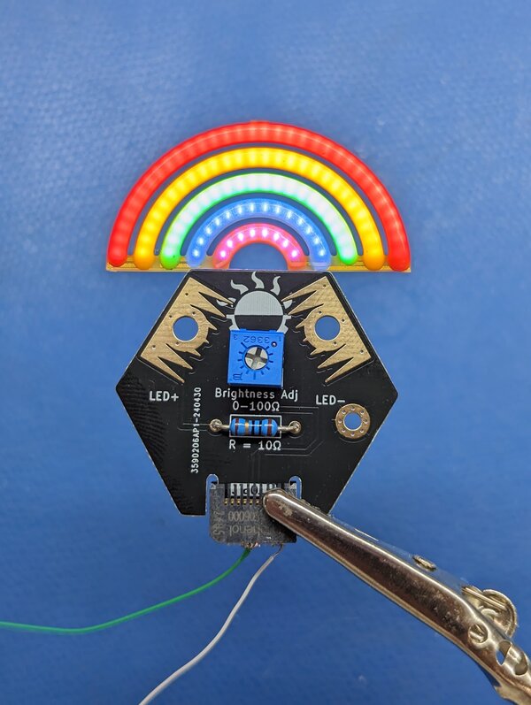
 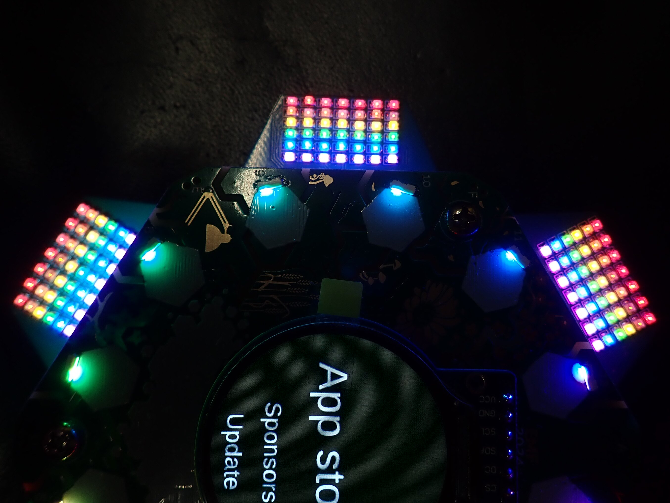 A pride rainbow by o0mouse0o
 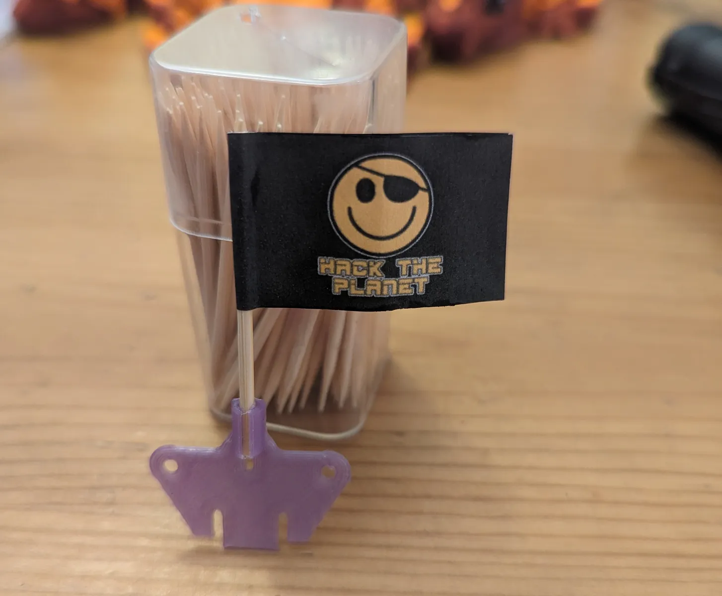 6flags Hexpansion by Ambrosia
 🖨️ PRINT ME
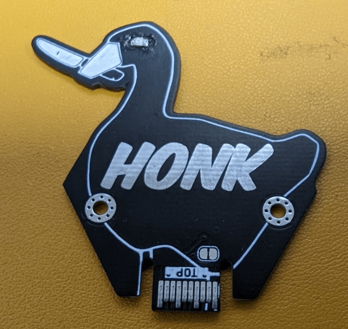 Simple Honk by The Untitled Goose
 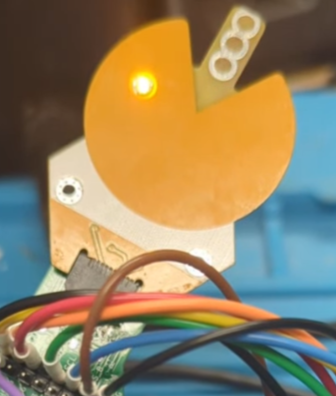 Pacman by The Untitled Goose
 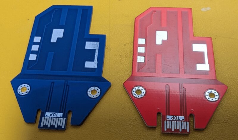 Doom Keycard by The Untitled Goose
  Hexnotoad by The Untitled Goose
 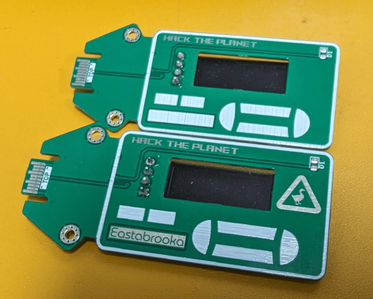 Hack the Planet by The Untitled Goose
 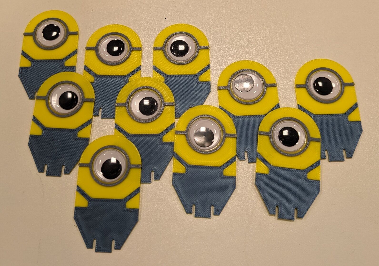 Henchmen by Brian Corteil
 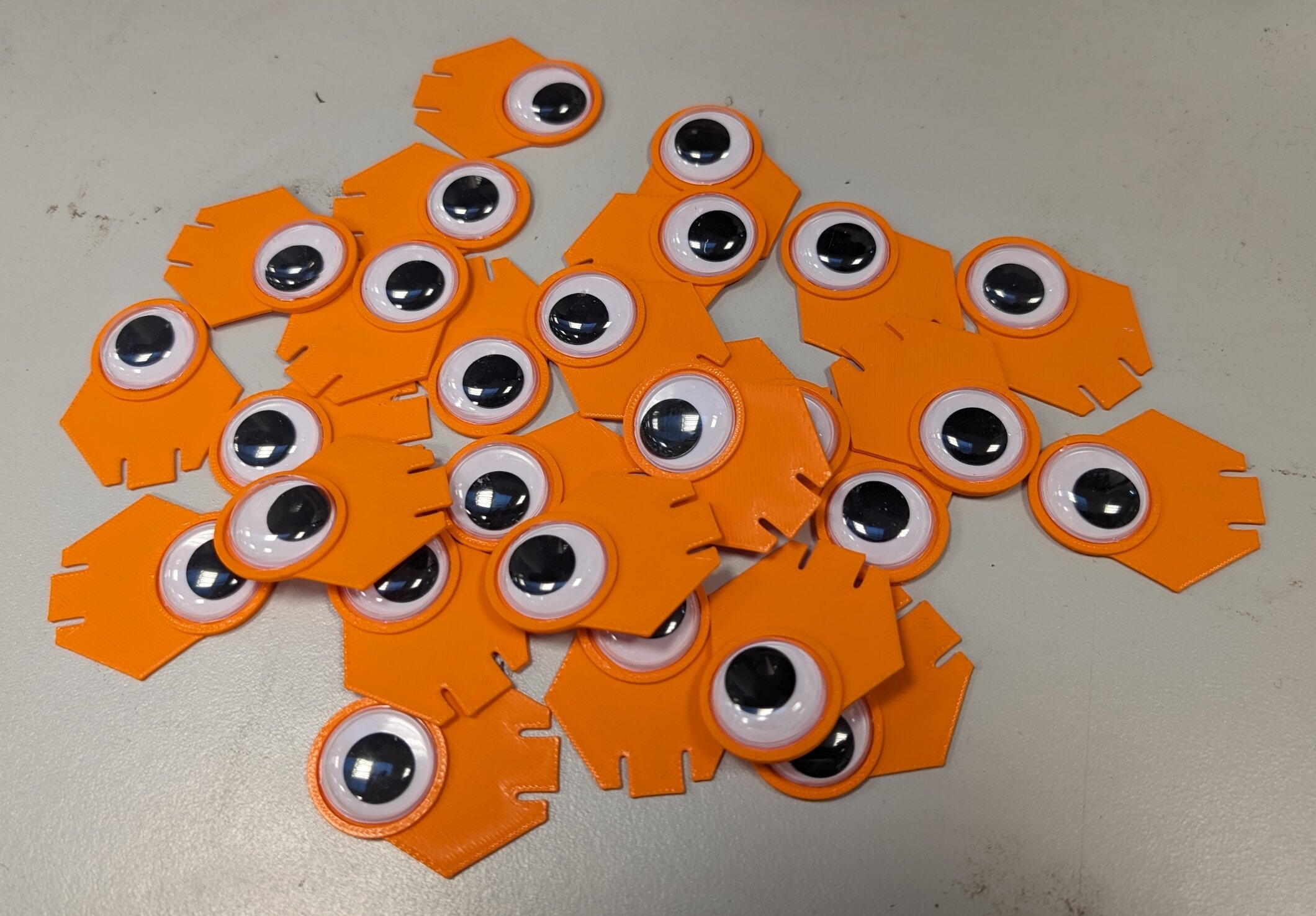 Googly Eye Alien by Brian Corteil
 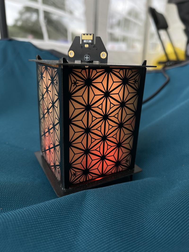 Lamp hexpansion by Tilde
 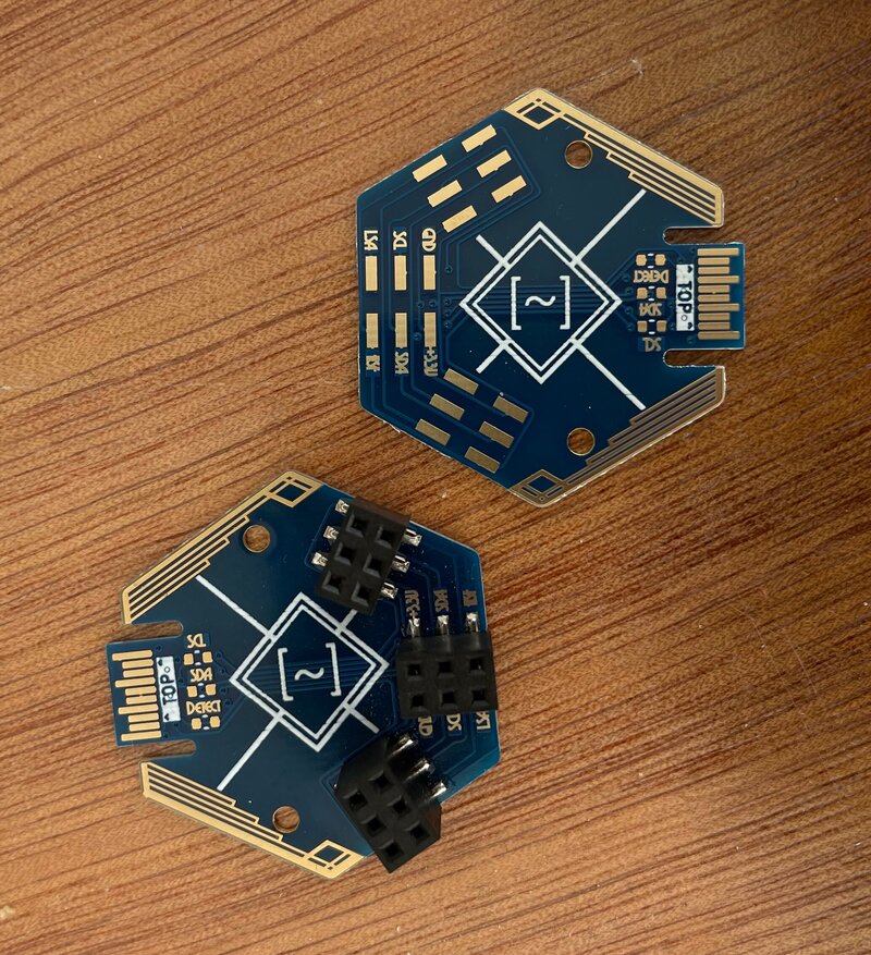 Breakout hexpansion by Tilde
 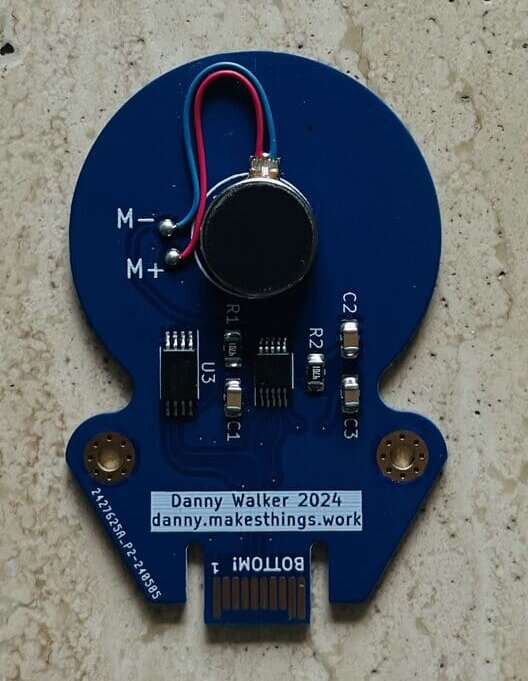 Caffeine Jitters by Danny Walker
 👀 VIEW FILES
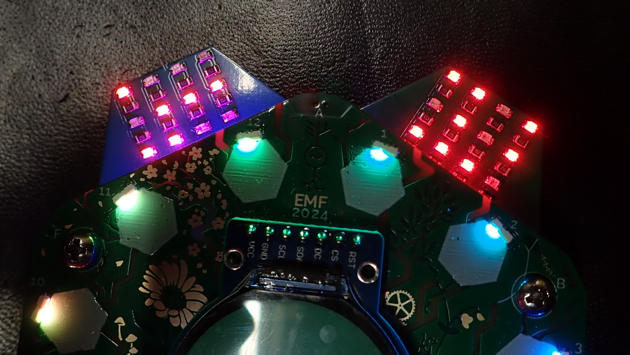
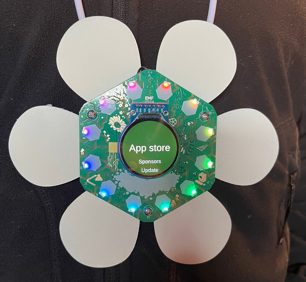 Petals by lornajane
👀 VIEW FILES
Petals on a badge
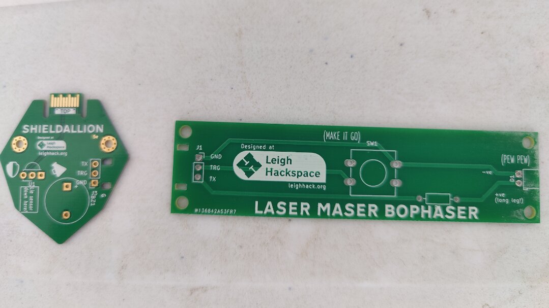 Laser Tag Shieldallion by kianryan
 Software link may be available later...
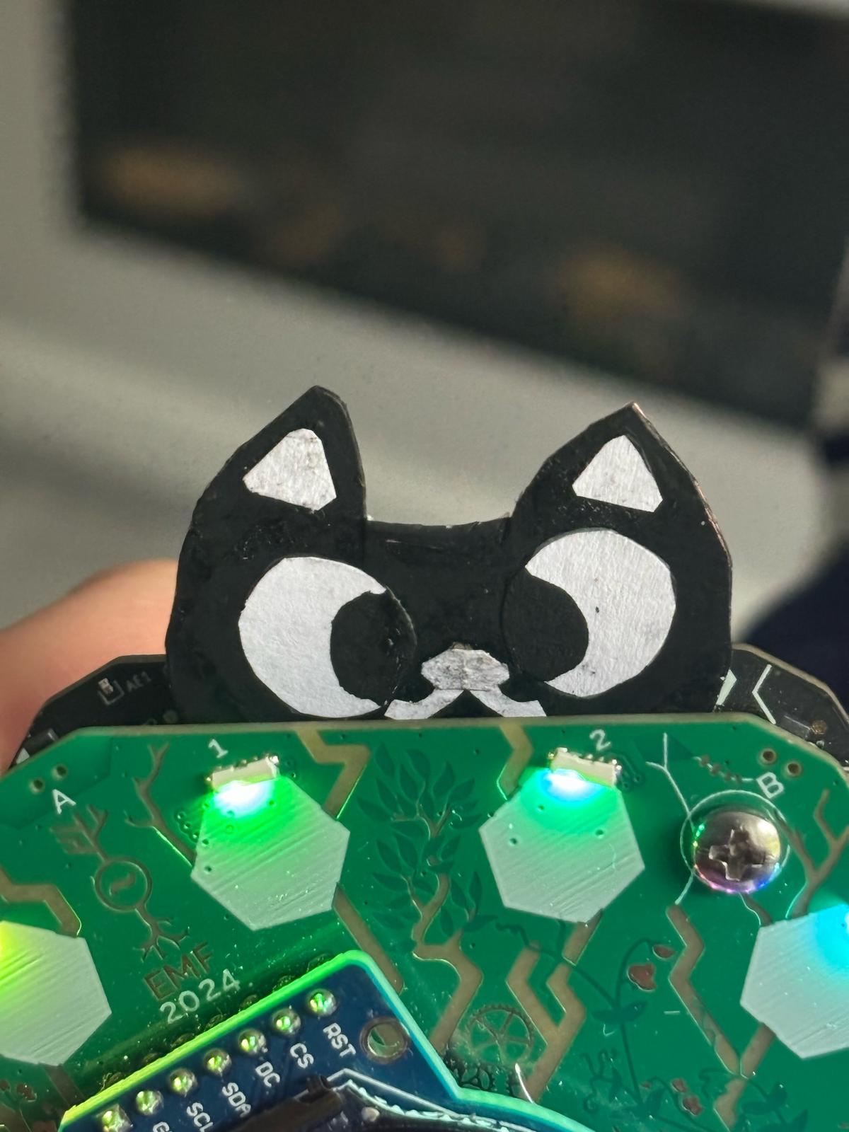 Cat hexpansion
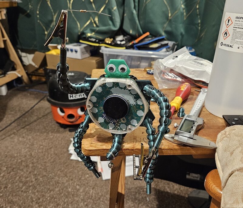
 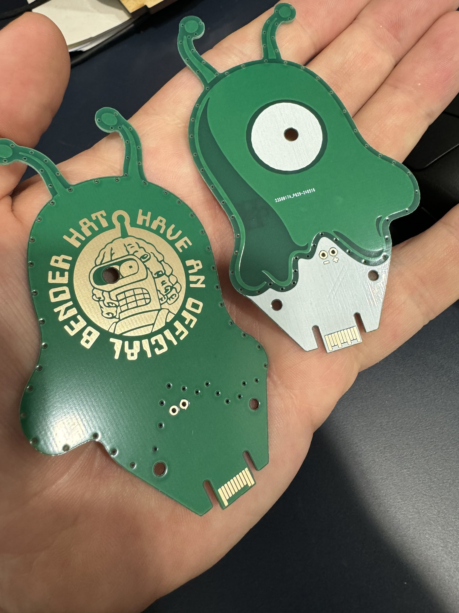 Brainslug by Paul Beech
 Link: Twitter
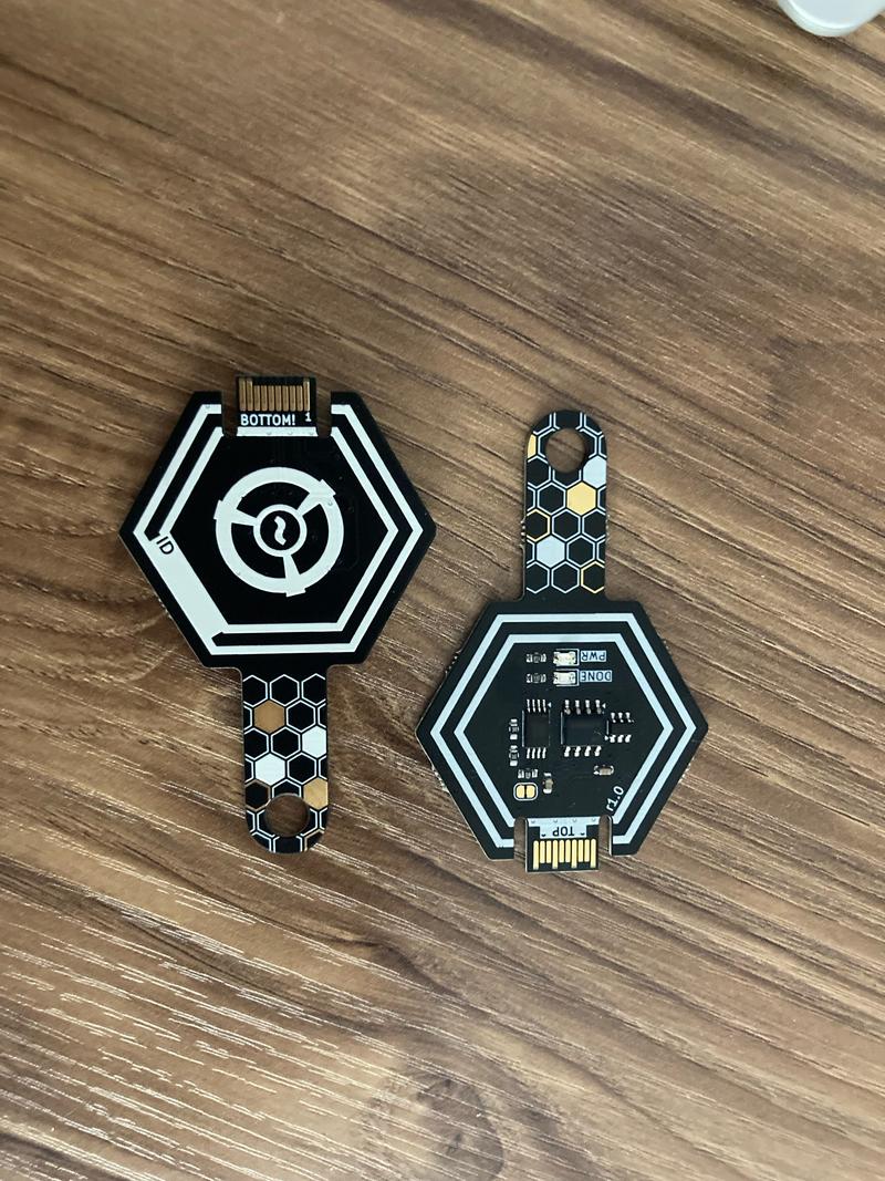
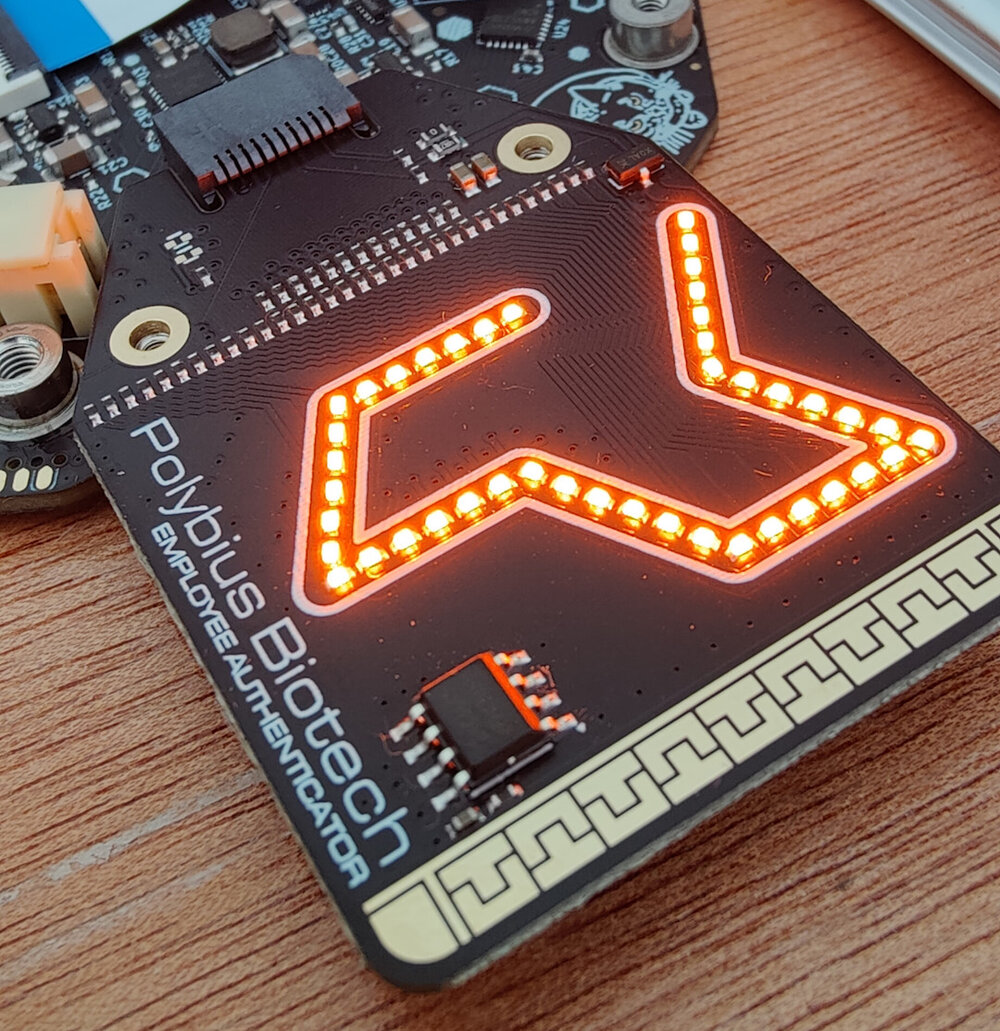 Polybius Biotech Employee Authenticator by Graham Sutherland (Polybius Biotech)
 DESCRIPTION REDACTED BY POLYBIUS BIOTECH SECURITY
 Helping HexpHANDsion by Yvan
 🖨️ PRINT ME
There are three categories of hexpansion:
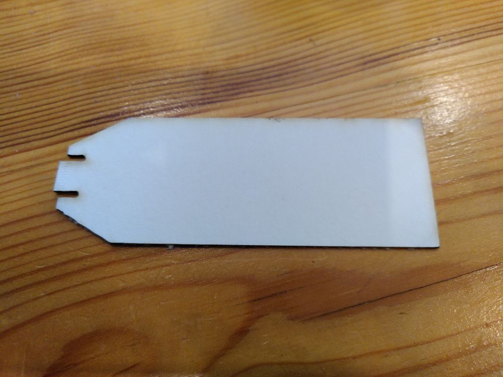
- purely mechanical ones which just have to be the right shape to fit;
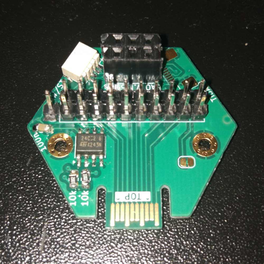
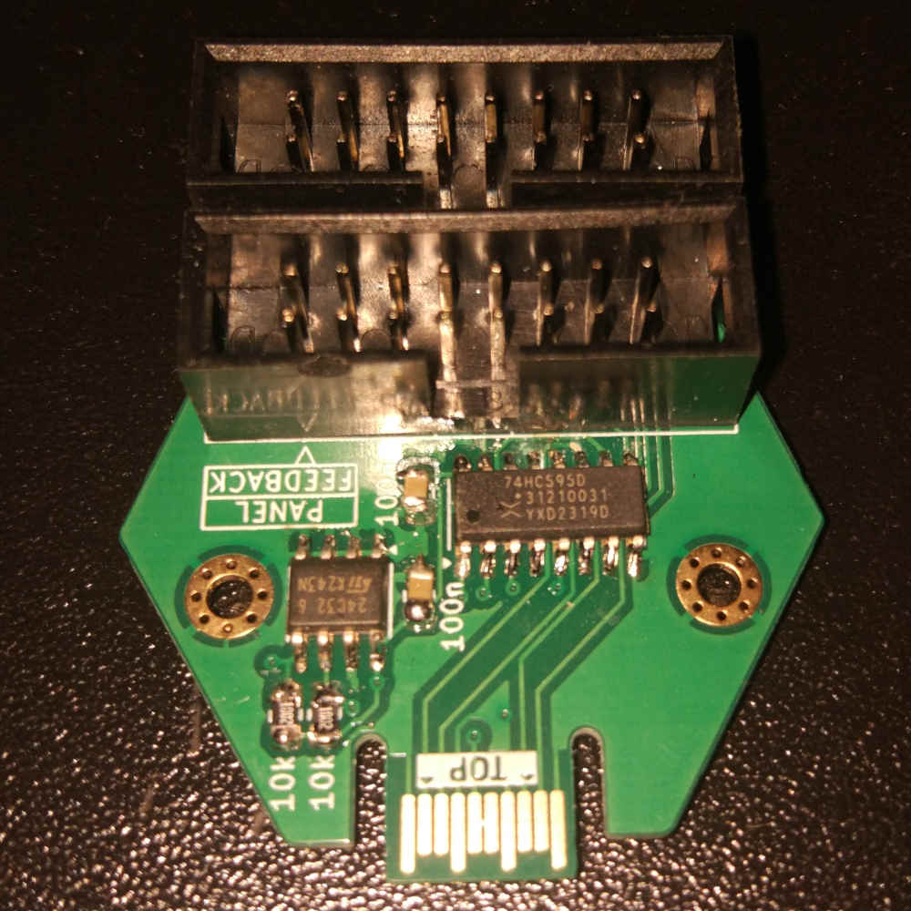
- PCB ones which use power and where the badge can detect insertion;
- electronically marked ones that the badge can identify and automatically do things with.
On the rest of this page, you will find the spec for the requirements these hexpansions must meet.
tl;dr:
- Hexpansions MUST BE 1mm thick! (more on this below).
- Hexpansions can be a PCB, or can be made of any other non-conductive material.
- Hexpansions that are a PCB must have ENIG finish.
- Hexpansions have to stay within their hexagon segment.
- There are part height restrictions on some parts of the board.
- Detect pin needs to be connected to GND on the hexpansion if you want power to your board.
- If you use I2C, you must provide I2C pullups.
- Hexpansions may not contain anything that uses the I2C address 0x77.
- Use the KiCad template project provided.
Hexpansion specs
A hexpansion must be 1mm thick! If it's any other thickness, it will not fit the port, and it will not work. The connector itself specifies a 0.1mm tolerance for thickness.
You can make a hexpansion by cutting out a shape out of any sufficiently stiff non-conductive material. The simplest hexpansion is a piece of 1mm card stock cut into a particular shape.
If you're laser-cutting a hexpansion out of plastic, note that cast acrylic sheet can vary quite a lot in thickness. Extruded acrylic sheet has better dimensional tolerance and is recommended for building hexpansions.
Templates for 3D printing Hexpansions
There are some example 3D printable STL files and a FreeCAD template on Printables, which may be useful as a starting point for prototyping.
Templates for PCB Hexpansions
There is a sample KiCAD hexpansion project, which is the easiest way of getting started making a Hexpansion PCB.
Shape and size
To fit into the slot, the hexpansion has to have a tab sticking out that is 9.2mm wide and 6.5mm long. That tab is 17.75mm away from the board edge.

The standard hexpansion shape is a hexagon with 32mm between flats. This means the distance between points is approximately 36.65mm. This shape puts the edge of the badge exactly down the middle of the hexagon. You can make the part on the outside any shape you like, but you have to keep it within the continuation of the lines of the hexagon, so that it won't interfere with other hexpansions. If you intend for something to plug into your hexpansion, make sure that the plug also does not cross into the adjacent segment.
The template project has guidelines to make this easier.
The "ears" around the connector tab are optional but help with mechanical stability.
If your hexpansion is a PCB, it must not have any depanelization tabs in the connector area.
Mounting holes
Hexpansions will be held in place snugly by the connector they plug into. In most cases they will not need additional mechanical support. However, if your hexpansion extends far outside the board, will be subjected to heavy mechanical loads, or has an external connector that can be subject to heavy loads, we have an additional mechanical attachment option.
There are two M2-size standoffs below the board, 25mm apart. They are 3.525mm from the centerline of the standard hexagon, and 14.25mm from the front edge of the connection tab. You can use two M2 size screws to attach your hexpansion to these standoffs for increased mechanical strength. Unfortunately, it's not possible to do this without removing the top board of the main badge, so installing and removing hexpansions with these screws is a bit more effort.
Connectors
Hexpansion connectors provide:
- Up to 600mA of 3.3V power (current-limited)
- An I2C bus (separate for each hexpansion)
- 4 high-speed GPIO pins connected directly to the ESP32-S3
- 5 lower-speed GPIO pins connected to a GPIO expander/LED driver
- 1 hexpansion detection pin (also used to switch power to the hexpansion on/off if needed)
A hexpansion can optionally provide an I2C EEPROM from the list of approved devices. If an EEPROM is present, the badge will be able to read a hexpansion identifier and name. You can also store code on the EEPROM, which will be copied to the badge and run from there.
For more information see EEPROM format.
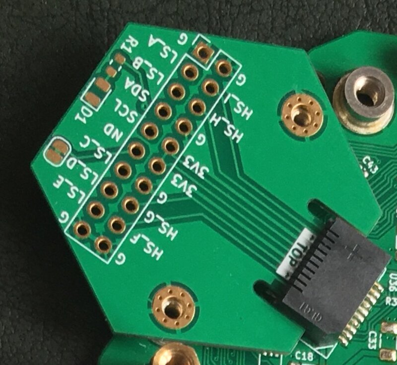
Electrical interface
If your hexpansion is electronic, it will connect to the Tildagon with some pads on the plugin tab. These pads will only make good contact if the board is flat, so the board must have ENIG surface finish. Do not use HASL finish!
The connector has the same pinout at the SFP interface used in networking equipment (if you feel like making an extremely cursed transceiver, go ahead!). The pinout is as follows:
| Bot side | Signal | Top side | Signal | |
|---|---|---|---|---|
| 1 | GND | . | 11 | GND |
| 2 | Low speed 1 | . | 12 | High speed 1 |
| 3 | Low speed 2 | . | 13 | High speed 2 |
| 4 | I2C SDA | . | 14 | GND |
| 5 | I2C SCL | . | 15 | +3V3 |
| 6 | Detect | . | 16 | +3V3 |
| 7 | Low speed 3 | . | 17 | GND |
| 8 | Low speed 4 | . | 18 | High speed 3 |
| 9 | Low speed 5 | . | 19 | High speed 4 |
| 10 | GND | . | 20 | GND |
The Detect pin lets the Tildagon know that a hexpansion has been inserted or removed. It also controls power to the hexpansion. The pin has a weak pullup, and you should connect it to GND on your hexpansion. If you want the ability to disconnect power from your hexpansion, you can add a circuit to disconnect Detect from GND.
The +3V3 pins can provide up to 600mA of current at 3.3V. If your hexpansion needs more power than that, you will have to provide it externally. 3.3V power to your hexpansion will be disconnected if you exceed this current level.
Pins 4 and 5 provide an I2C interface. Each hexpansion port has a separate I2C interface. You can put any I2C devices you like on that bus, and they can use any I2C address, except 0x77. The badge needs that address to talk to the I2C mux, and if a hexpansion responds to it, the Tildagon has to disconnect its I2C bus. There are no pullups on the I2C bus - you have to provide those yourself.
If you want code on the Tildagon to be able to recognize your hexpansion, you can add an I2C EEPROM. We have currently tested two EEPROM ICs, but many more will work if they have the same address and interface as one of those. The ones we tested are:
- ZD24C64A-XGMT
- M24C16-RMN6TP
You can also put code on the EEPROM and give users the option to copy that code to their Tildagon and run it.
Each hexpansion port has its own isolated I2C interface and its own separate I/O pins.
There are five low speed pins (LS1-LS5) that are connected to a GPIO expander IC which provides interrupt detection and also has a constant current driver for controlling LED brightness. Switching them is a bit slow, but definitely fast enough for indicators, buttons, buzzers, and similar. These pins do not have pullups or pulldowns - if you need these, you will have to provide them yourself.
There are four high-speed pins (HS1-HS4) that are directly attached to the microcontroller on the Tildagon. Please do not try to source or sink too much current from these pins. You can connect these to any of the peripherals on the ESP32-S3 that are not already in use. Three of the six ports on the Tildagon have high-speed pins that are attached to the internal ADC (analogue to digital converter, for measuring analogue signals). They are the connector behind the row of three buttons, and the connectors either side of that (highlighted in the image below).

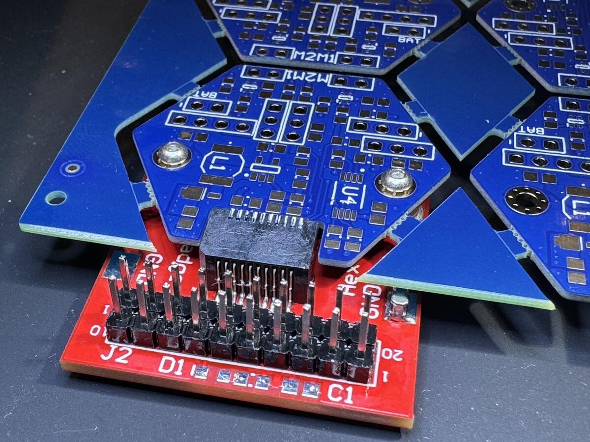
Mechanical clearance
There is a battery between the top and bottom boards of the Tildagon, and therefore there are restrictions to how tall components on hexpansions can be. Here are the height restrictions and their relevant areas:

The two upper hexpansion slots are directly over the two USB connectors. Due to the cable overmold, there may not be anything sticking out below the board in those slots. Hexpansions that go into other slots have 1mm of clearance below the PCB surface up to the Tildagon board edge, and unlimited clearance beyond the edge. If you have through-hole components on your hexpansion PCB, they cannot be used in the slots over the USB connectors as the solder tails below the board will interfere with the USB cable overmolding.
Congratulations
Well done on creating your hexpansion! We encourage you to share your creation in the Hexpansion Showcase in these docs, or in the Hexpansions Registry.